Tubing anchor catchers, or TACs, are a vital component of many downhole tool assemblies. In wells that use sucker-rod pumps for artificial lift, TACs enhance artificial lift efficiency, reduce wear and tear on equipment, and prevent tubing failure. However, achieving those benefits requires that the tubing anchor catcher is installed correctly. This guide will outline key steps for preparing, running, setting and releasing a TAC. Unless otherwise noted, these instructions apply to both standard B2-style TACs and Slimline® Tubing Anchor Catchers.
Preparation: Before Running the TAC
It is recommended that the casing be prepared and cleaned prior to running in with a TAC (e.g., bit and scraper, string mill, etc.) to ensure the tool will actuate properly.
Do not use the drag springs as carrying handles for this tool. The springs could be permanently distorted, which can result in serious difficulty running the tool.
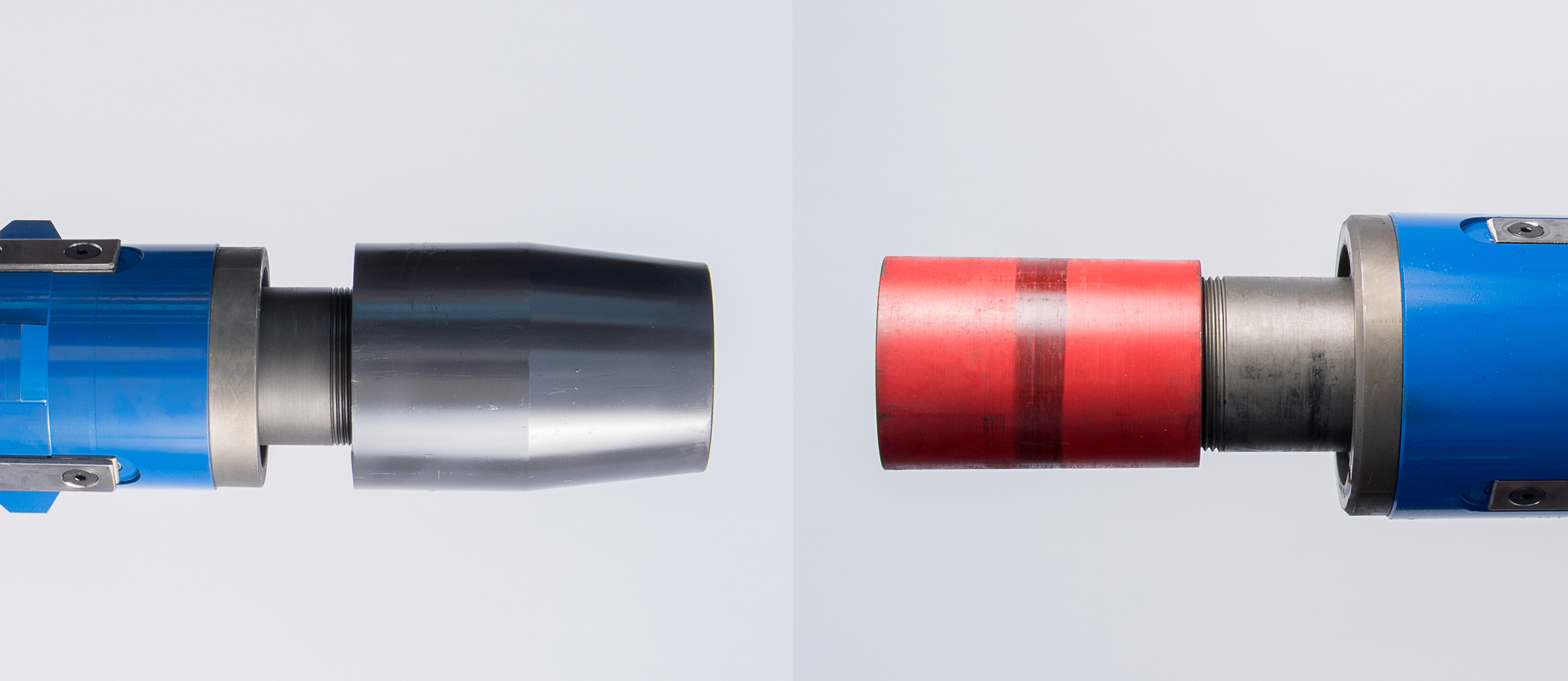
The box-end sub is the top of the TAC; the pin is bottom.
Do not tighten through the TAC when attaching it to the tubing string. When attaching tubing to the TAC, put a backup on the TAC subs. Doing so will help prevent over tightening and possible galling of the 10-round inner threads on the TAC.

To avoid accidentally setting the anchor while running in/out, ensure the rig backups function properly and are utilized.
Always confirm the TAC placement in relation to the pump and/or any other downhole assembly. Slimline TACs may safely be set below the seat nipple to accommodate pumps/tools larger than the TAC ID.
Deployment: While Running the TAC Downhole
NOTE: Unless requested otherwise, all TACs will be LEFT-HAND SET.
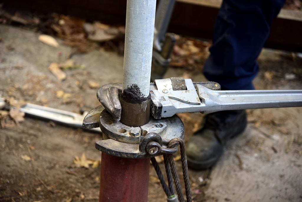
To prevent the TAC from setting while running in, it is recommended to occasionally (every 5-10 stands) use a pipe wrench to put a right-hand turn in the tubing (if running a right-hand set TAC, put a left-hand turn in the tubing).
SLOW DOWN, especially when going through a tight spot or when hitting fluid.
Placement: Setting the TAC
Once the desired setting depth in reached, rotate the tubing to the left (to the RIGHT if the TAC is right-hand set) until the slips contact the casing. The approximate number of turns AT THE TOOL to set the anchor are:
- 6-8 turns for 7.0” and 5.5” TACs
- 8-13 turns for the 4.5” Slimline TAC
- 1.5-3 turns for quick-setting anchors like the 5.5” or 7.0” Slimline® QuickSet™ TACs
Due to well depth, deviations and dogleg severity (DLS), the number of tubing turns applied at the surface may not correspond to the same number of turns at the tubing anchor catcher. This consideration needs to be factored in when setting the TAC to ensure proper engagement.
Whenever possible, set the TAC using pipe wrenches. However, if power tongs are needed, make sure the torque on the tongs is several hundred pounds less than what the tubing string was initially tightened with. This approach will help prevent the tubing from backing off.
The tubing will torque up when the slips have set. To ensure all tubing torque works its way down to the tool, maintain left-hand torque and alternate several times between setting down and pulling up.
During this slip-setting operation, the strain pulled should be at least equal to the final strain that will be applied when the tubing is landed.
Set back to neutral, torque again and then the tubing is ready to be landed. As an added measure to help prevent the TAC from backing off during pump operation, hold tension for at least 2 minutes to ensure slips permanently bite the casing. Finally, put an additional 1/2–3/4 turn immediately before landing the tubing.
NOTE: Tubing tension should always be applied in inches of stretch rather than pounds of pull to ensure accurate tension is applied, as not all weight indicators are accurate.
Stretch Formula
The following formula and example can be used to calculate tubing tension using inches of stretch:
Length = pull force in thousands of lbs. x length of feet in thousands x stretch constant* in inches of stretch per thousand pounds of pull per thousand feet of length.
(Example) 20,000 lbs. of pull on 8,000 ft. of 2.375” OD, 4.7#, 1.995” ID tubing.
20 x 8 x 0.30675 (stretch constant for 4.7# 2.375 tubing) = 49.08 inches of stretch
*Stretch constant for 6.5# 2.875” tubing is .22075
Removal: Normal Releasing Procedure
To ensure the lower cone will be completely retracted when the slips lose their grip on the casing, the anchor catcher should be released with the tubing in slight compression as the upper cone contacts slips. This feature prevents dulling of the slips during retrieving due to incomplete retraction of the lower cone.
If this is not possible, however, the tool can be released without compression or even with the tubing string in tension.
Rotate the tubing to the right (to the LEFT if the TAC is right-hand set) 5-8 turns at the tool to retract the cones from the slips and allow the slips to move back into the housing. For quick-setting TACs, only 1.5-3 turns are typically required to retract the cones.
To ensure the slips are all the way backed off while the tubing anchor is coming out, occasionally (every 5-10 stands) use a pipe wrench to turn the tubing to the right (to the LEFT if the TAC is right-hand set).
Removal: Emergency Release
If the tubing anchor catcher does not release in the normal manner, an up-strain greater than the total shear strength of the shear pins plus the weight of the tubing will shear the pins and release the TAC.
Special Considerations for Deviated Wells
When running the Slimline TAC or Slimline QuickSet TAC in an extremely deviated and/or horizontal well, special attention should be paid to a few important factors. In addition to closely following the directions outlined above, operators and rig crews should also consider the following:
It is not recommended to exceed 30 degrees when running a Slimline QuickSet TAC in the bend of a horizontal well. Because the Slimline QuickSet TAC can be fully set in 1-3 turns, it’s proven to be an ideal solution for deep or deviated wells, where it can be difficult to get enough torque down to a tool to set a traditional anchor. However, setting the TAC so deep that its vertical alignment exceeds 30 degrees can create an undue bending moment on the anchor. That’s why many of the production companies that use TechTAC anchors prefer to set them just above the kickoff point in a horizontal well.
It should also be noted that for some wells even setting the anchor at 30 degrees may be too much, depending on the geometry of the wellbore. Always confirm the TAC placement in relation to the pump, well deviations and/or any other downhole assembly.
Ensure that enough upward tension is pulled on the TAC before landing the tubing. Before landing the tubing, it’s vital to pull the proper tension on the tubing anchor. Without the proper tension, the cyclic loading inherent during sucker-rod pumping can exceed the tension placed on the TAC. This means that instead of remaining under constant tension as designed, the TAC alternates between tension and compression with every pump stroke. This cycle places undue wear and tear on the TAC and, over time, can lead to tool failure—either through premature shearing, or worse, causing the top sub to break off.
However, it is essential that this tension is measured in inches of stretch and NOT pounds of pull. Particularly in a well with high DLS or cork-screwed geometry, all the bends the tubing must navigate can make the surface measurement of pounds of pull highly inaccurate when compared to the tension at the tool. Instead, a calculation like the one noted above should be used.
Do not over-torque the tool. Most tubing anchor mandrels (bodies) are connected to the subs with NU 10-round threads, whereas most tubing connections are EUE 8-round threads which can handle higher amounts of torque. This knowledge is particularly important when attaching tubing to the anchor.
It’s recommended to put a backup on the TAC subs, while independently connecting the tubing to both the top and bottom TAC connections. Doing so will help prevent over tightening and possible galling the 10-round inner threads on the TAC.
To access additional resources and technical documentation for the tubing anchor catchers in TechTAC’s product suite, visit the Product Documentation section of the company’s website.
Source: Much of the content in this document has been sourced from “Baker Hughes Technical Unit Service Tools / Remedial Systems – General Service Equipment and Accessories – Unit No. TU 4160 Feb. 10, 2011.”


